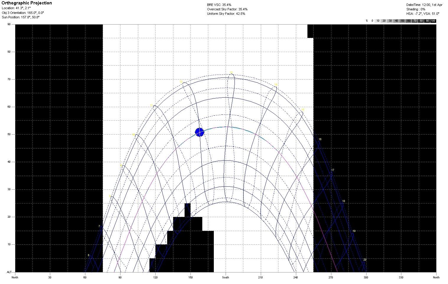
In preparing an energy certificate for a building, one of the most cumbersome calculations is that of the shadow pattern, although it is very simple. To calculate a relatively complex shadow pattern (with non-orthogonal obstacles) the usual method is to make a conical projection on a representative point of the facade to be studied.
The shadow pattern is a projection of remote objects that can cast shadows on the building onto a solar stereographic projection. In this way we will compare the path of the sun at all times of the year and the objects likely to shade our building.
Thus, the most appropriate procedure is: first to make an axonometric representation (preferably with a CAD program) of the objects that we want to study, defining the vertical edges and the representative point. Then we start with the first step of the measurement process: we measure the angles in plan α (from the north-south axis) and in elevation β (in the plane that is defined by the triangle that forms the representative point and the edge of the volume that gives shade). We repeat this process as many times as there are edges in the volume that gives us shade.

Once we have measured all the angles α and β, we can tabulate them in the table provided by the CE3X program. The projection of the volumes will automatically be drawn on the solar trajectory diagram. It is a simple process: for each plane you must create a line in the table.
We can also introduce in the shadow pattern (if we want to be more rigorous) the exact shadow that our own facade projects (in the bottom drawing they are the two large rectangles that are left and right), that is, define exactly that 180º of sky are visible by the plane of our facade. For example, in our case we have a façade with an azimuth -15º, it is therefore oriented to the South as defined in the Technical Building Code since it is within -18º of deviation, therefore this façade it will have an opening to the celestial vault of 180º but nevertheless displaced 15º with respect to a facade oriented to azimuth 0º.

The shadow pattern in energy certification becomes very complicated when there are complicated, non-aligned volumes around our building. In this case a possible option is the modeling in Ecotect and the calculation of the orthogonal projection in the Sun Path Diagram calculation option. In this way we will save the painful work of measuring angles.
We model the volumetry in the Ecotect program and once we have the diagram represented we will only have to take the angles α and β (the values on the “x” and “y” axis respectively) and enter them in the CE3X shadow pattern sheet.


Leave A Comment